
 English


How to Solve Common Ultrasonic Welding Problems
Ultrasonic welding is a widely recognized and accepted process for joining thermoplastic materials. It offers many advantages, including process reliability and repeatability, lower energy usage than other joining techniques, material savings (because there is no need for consumables, such as glue or mechanical fasteners), and labor savings.
But as with any process, there are situations where apparent problems with this technique may interrupt the production process. The key to resolving and avoiding these problems is to understand their likely origins. Processors that are successful in using ultrasonic welding typically share two principal traits: they have a well-documented, validated welding process; and that process is supported and maintained by a resident well-trained “champion.” If one or both of these important factors are not present, you’ll likely very soon call for help. Even with both present, it is possible that you’ll need some help or technical assistance at least once in a while.
HOW THE PROCESS WORKS
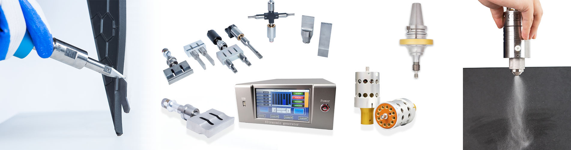
Before examining common causes of ultrasonic welding problems, let’s take a moment to understand the welding cycle itself. In ultra- sonic welding, high-frequency vibrations are applied the surfaces of two parts by a vibrating tool, commonly called a “horn” or “sonotrode.” Welding occurs as the result of frictional heat generated at the interface between the parts. The ultrasonic vibrations are created by a series of components—the power supply, converter, booster, and horn—that deliver mechanical vibration to the parts.
The power supply takes a standard electrical line voltage and converts it to an operating frequency. In the following example, we will utilize a common ultrasonic welding frequency of 20 kHz, though welding can take place over a range of 15 to 60 kHz to meet specialized needs. In operation, the power supply sends electrical energy at the specified frequency through an RF cable to the converter. The converter utilizes piezoelectric ceramics to convert the electrical energy to mechanical vibrations at the operating frequency of the power supply. This mechanical vibration is either increased or decreased based on the configuration of the booster and horn. The proper mechanical vibration amplitude is determined by an applications engineer and is based on the thermoplastic materials used in the parts.
The parts to be welded are put under a mechanical load, generally with a pneumatic actuator that holds the booster and horn. Under this load, the mechanical vibrations are transmitted to the interface between the material surfaces, which focuses the vibrations to create intermolecular and surface friction. This friction creates heat and a subsequent melt, which solidifies into a welded bond.
The basic components of an ultrasonic system are a power supply, an actuator, and a stack. The power supply takes line voltage at a nominal 120-240V and transforms it into a high-voltage, high-frequency signal. It also contains the programming necessary to operate the actuator and stack in a controlled manner to achieve a desired weld result. The actuator, either pneumatically or electric servo-operated, and available as a stand-alone benchtop unit or integrated into an automated system, moves the ultrasonic tooling toward the parts to be joined. It applies the needed force to the materials to help create the welding conditions.
The ultrasonic stack completes the system. It transfers vibratory energy, through direct contact with the parts, to the sealing/joining surface. The stack typically consists of three items: the transducer or converter (described above), which contains the piezoelectric ceramic crystals that oscillate at the frequency of the applied power-supply signal. As these crystals oscillate, they physically expand and contract, creating measurable mechanical motion (referred to as peak-to-peak amplitude) in the output side of the transducer.
The second section, the booster, with an attached ring in its mid-section, serves two functions: It acts as a mounting point for the stack into the actuator, and also serves to amplify or reduce the output motion created in the transducer.
The third and final component of the stack is the horn (sonotrode) that will contact the parts to be joined. The horn will be designed to match the profile of rigid parts to be joined or can have a sealing profile added to its contact face in a film/textile application. For each application, the horn is designed to combine with the other stack components to reach the optimum level of amplitude output to allow ultrasonic welding to occur as efficiently as possible.
Previous :
Plastic WeldingNext :
The origin of ultrasonic atomization Floor 1st, Building 2#, NO.2626 Yuhangtang Road, Yuhang District
For inquiries about our products or pricelist, please leave to us and we will be in touch within 24 hours.


© Copyright: 2026 Hangzhou Altrasonic Technology Co.,Ltd All Rights Reserved

IPv6 network supported
Scan to WhatsApp


