
 English


Ultrasonic welding design principles
Ultrasonic welding design principles
1. Basic investigation of design
In order to achieve good welding results, the factors that must be examined are as follows:
2. Welding parts design focus
Designed to be able to transmit ultrasonic energy
If the welding surface has some distance from the contact surface of the ultrasonic welding head, the shell member must be hard enough to transmit ultrasonic energy. The soft plastic cannot transmit energy reliably. The thickness of the shell wall must be sufficient to prevent deformation of the welded area. Thin wall is easy to weld. The mechanical force in the process breaks.
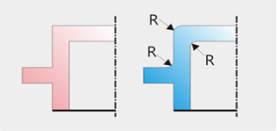
(1)The corners and edges of the weld
All corners and edges must be rounded, and sharp edges can accumulate ultrasonic energy and cause cracking or unnecessary welding.
(2)Potential product design issues
Parts that extend beyond the body, such as ribs, brackets, studs, are susceptible to breakage due to vibration or overheating during ultrasonic welding. In addition, other built-in objects such as springs or wires are also the cause of the welding effect. In a nutshell, smooth edges and corners, small amplitude, and short welding time can achieve the best welding results. If necessary, silica gel can be used to buffer the vibration of electronic parts, springs, etc.
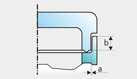
(3)The welding condition of the weld
Ideally, the two shells must fit together and not be slipped during the welding process. The ideal anastomosis is that the two can be tightly bonded by external force but not too tight. The ideal gap is 0.05 to 0.1 mm. Depending on the size of the weld, the height difference between the two welds is at least 1.0 mm.
Recommended gap a = 0.025 ~ 0.05mm; b = min. 1.0mm
(4)Energy transfer needs to be uniform
The design of the joint affects the uniformity of energy transfer. In general, bends, bevels or openings in the energy transfer path reduce the intensity of the ultrasonic waves transmitted to the weld surface.
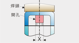
The X area in the figure is prone to insufficient soldering or soldering.
(5)the position of the joint surface
The best condition is that the joint surfaces are all at the same height and parallel to the surface of the weld head. If this is not the case, because the distance from the joint surface to the surface of the weld head is different, it is easy to have uneven welding.
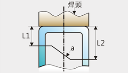
In the figure, the distance between L1 and L2 is not equal, and the a surface is not parallel to the surface of the welding head, and the energy loss transmitted to the contact surface of the two shells is shown.
(6)the weldment and the weld head contact surface
The best condition is that the contact surface of the shell and the horn is large and flat, and the surface of the horn can be partially contoured. If the surface of the horn is smaller than the joint surface, although the welding can still be achieved, part of the energy may not be transmitted to the joint surface, and it is necessary to increase the pressure to achieve a good welding effect, but increasing the down pressure may cause an indentation on the surface of the weldment. Polished or uneven surfaces are particularly prone to weld head indentations, and the addition of PE molds reduces indentation.
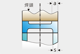
The shell member that is in contact with the horn should be as large as the horn contact surface, for example, a must be as wide as possible s.
 Floor 1st, Building 2#, NO.2626 Yuhangtang Road, Yuhang District
For inquiries about our products or pricelist, please leave to us and we will be in touch within 24 hours.


© Copyright: 2026 Hangzhou Altrasonic Technology Co.,Ltd All Rights Reserved

IPv6 network supported
Scan to WhatsApp


